
How to use jumper cables
Connect the positive points first, then the donor’s negative point, and make the final connection at the disabled car’s approved ground point.
These steps cover conventional 12V, negative-ground vehicles using ordinary jumper cables and a compatible donor car. Check both vehicle manuals and the cable instructions first: designated jump points and operating sequences take priority. This is not a procedure for high-voltage systems, hybrids, EVs or positive-ground vehicles.
Using a battery pack instead of another car? Follow the portable jump starter instructions.
1. Prepare both cars
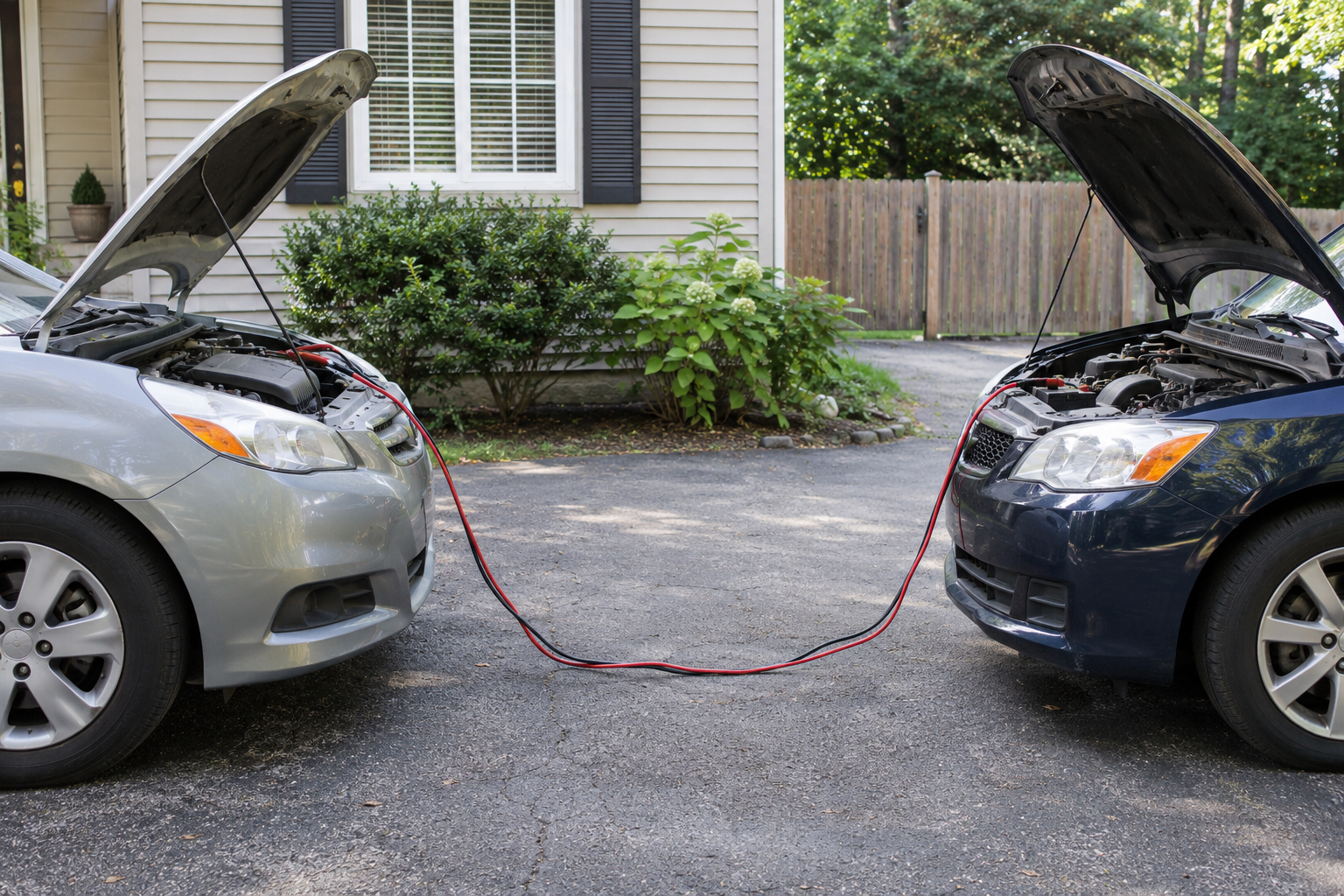
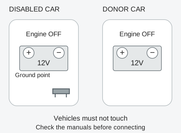
Park safely with enough cable reach, without letting the cars touch. Apply the parking brakes, select Park or Neutral as appropriate, and turn off the engines and accessories. Identify the marked positive points and the disabled car’s designated ground before picking up a clamp.
Do not proceed with a frozen, leaking or damaged battery, damaged leads, or an unsafe roadside position. Wear eye protection, remove metal jewelry and keep flames away. If you cannot identify the correct connections, call roadside assistance.
2. Attach red to the disabled car’s positive point
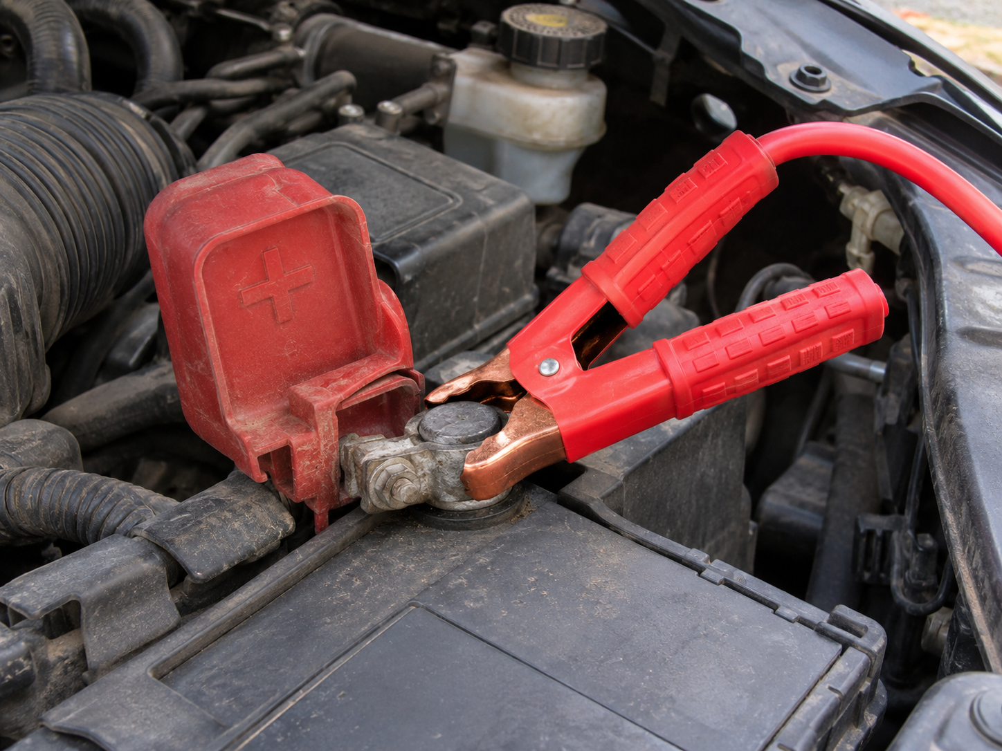
Find the + marking, rather than relying only on a cover’s color. Attach one red clamp to that positive terminal or designated positive jump point. Keep the loose red clamp away from metal.
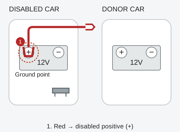
The diagrams show connection locations, not an engine-bay layout. Use your vehicle’s designated points. If your cable instructions specify a different red-end order or a particular donor end, follow those instructions.
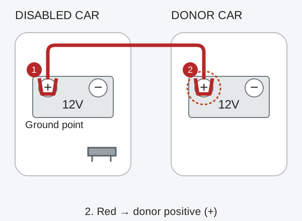
3. Attach the other red clamp to the donor’s positive point
The red cable now links positive to positive. Check both clamps are secure and their exposed jaws cannot touch nearby bodywork.
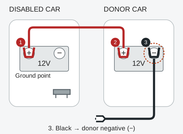
4. Attach black to the donor’s negative point
Connect a black clamp to the donor battery’s − terminal, or the negative connection specified by its manual. Keep the remaining black clamp separate until you are ready for the final connection.
5. Make the final connection at the disabled car’s ground
Attach the remaining black clamp to the approved ground point, away from the battery and fuel system. Do not substitute a fuel line, thin body panel or a random bolt. If no ground point is clearly identified, stop and check the vehicle manual.
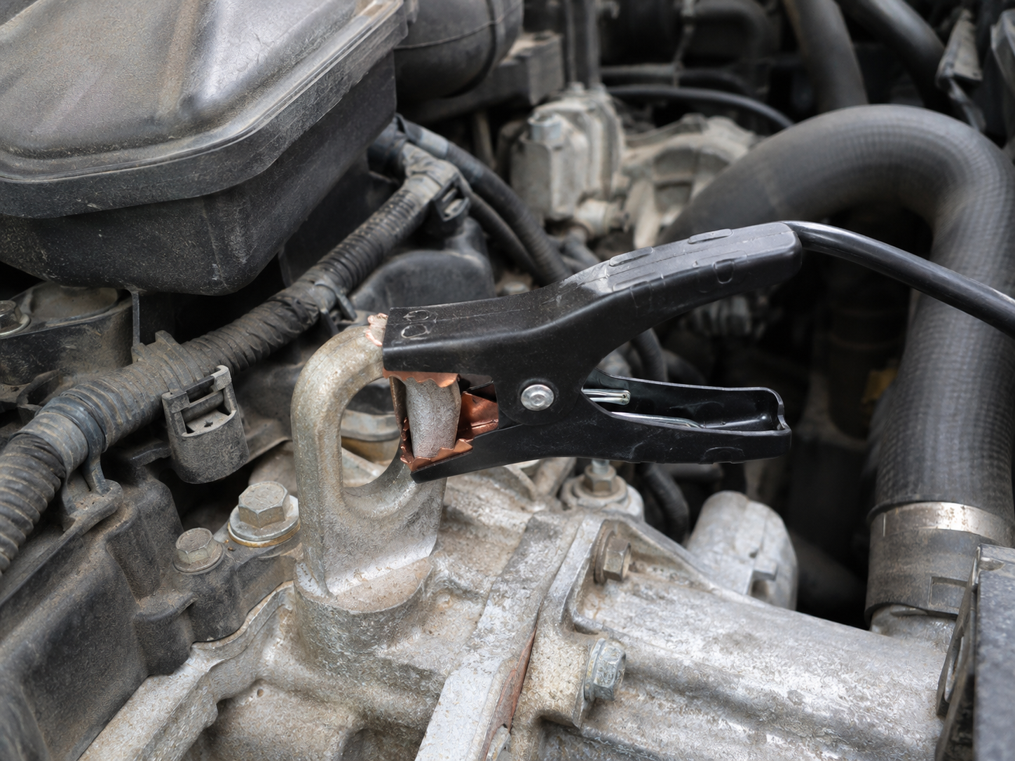
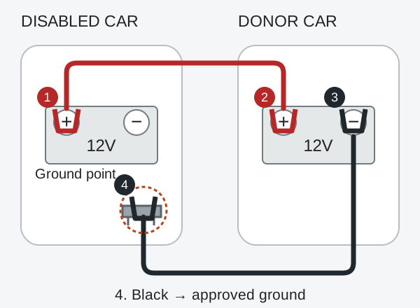
Keep all leads clear of belts, fans and hot components. The final connection is away from the battery because a spark near battery gases can cause an explosion.
6. Start the donor, then attempt to start the disabled car
Follow the vehicles’ instructions for donor engine operation and waiting time before the starting attempt. Respect the stated cranking limit and rest interval. Do not keep turning the key repeatedly if the engine will not start.
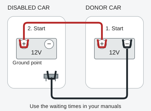
If the cables become hot, switch off both vehicles and stop trying. If a correct connection still does not produce a start, seek assistance rather than assuming more attempts will fix it.
7. Remove the cables in reverse order
Once the car starts, follow the specified running time and engine on/off instructions before disconnecting. For the connection sequence shown above, remove:
- Black clamp from the disabled car’s ground.
- Black clamp from the donor’s negative point.
- Red clamp from the donor’s positive point.
- Red clamp from the disabled car’s positive point.
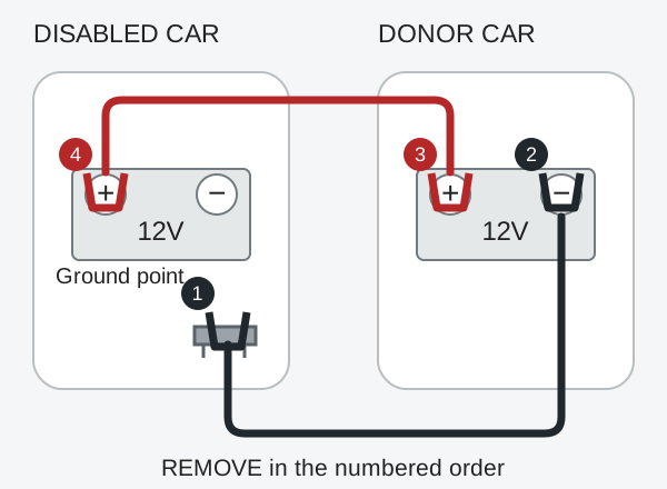
Keep released clamps apart and away from metal, moving parts and hot surfaces. If you connected the red ends in a different manual-approved order, reverse that actual sequence.
If you have no donor car
Ordinary jumper cables need an external power source. A portable jump starter supplies its own battery, but has a different connection and operating procedure. To choose one to keep in your car, compare our portable jump starter picks.